
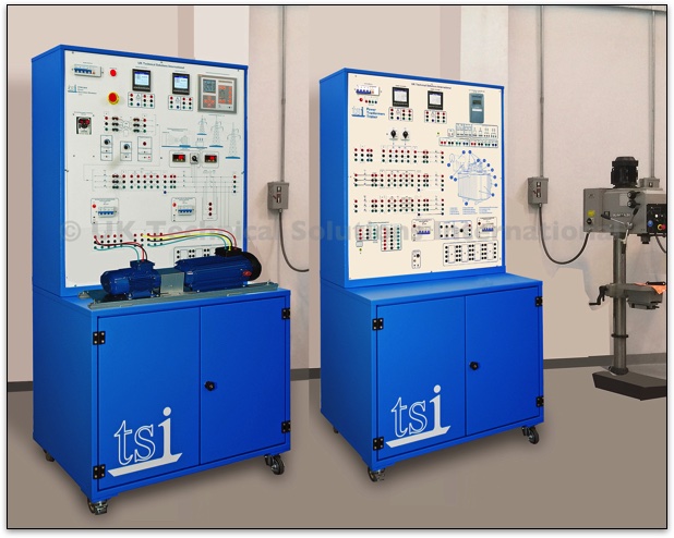
Electrical Machines and Transformers Lab
This is a complete practical laboratory that provides all the resources needed to deliver a comprehensive training programme that covers the principles of electrical machines and transformers.
We include our unique MCL/100 Motors and Generators Trainer to enable instructors and trainees to perform a wide range of experiments and practical troubleshooting tasks on an advanced system that directly relates to Power Generation applications as opposed to abstract theoretical ones..
The PTL/100 Power Transformers Lab provides an excellent introduction to single phase and three phase power transformers and their applications in power systems.
The trainer features three power transformers and a phase shifting transformer. Students can experiment with different Wye/Delta configurations and build step up and step down transformers as well as connecting transformers in series and parallel.
These help provide the trainees with the basic knowledge and skills to enable them to work on real industrial equipment in other OJT Workshops.
TSI-MCL/100 Motors and Generators Training Module
This unit has been specifically designed to provide a practical training resource that covers electric motors and generators.The workstation incorporates a machine mounting bed where different DC and AC motors can be easily aligned and connected to a fixed 3-Phase Generator.
An automatic circuit breaker main switch provides overall power to the module.It also includes an emergency stop button. All circuit interconnections are made using 4mm safety leads and sockets.
The outputs from the electronic variable motor drive can be connected to the AC motor to allow for changes in the speed and torque of the fixed synchronous machine.
This is a fully programmable control and it can be used with the range of additional three-phase and single phase AC motors available for use with the MCL/100. A tachogenerator is located in between the motor couplings to provide a speed feedback signal.
A separate variable DC excitation control is also provided to allow for changes in the voltage and reactive power of the 3-Phase Generator.
The outputs from this drive are available on the front panel and can be used to drive an the additional DC motors available for use with the MCL/100.
The unit is supplied as standard with the following specification AC Motor:
- V = 220/380V
- F = 60Hz
- Nominal maximum speed: 3,600 RPM approx.
- Rated power: P = 1.5 KW
-
= 7/4 A approx.
- Rated power: P = 1KW
- Nominal maximum speed: 3.600 RPM
- Vin = 220/380V
- f = 60 Hz when functioning as motor
- Vout = 220/380V
- f = 60 Hz when functioning as generator
- Iout = 2.8/1.6 A approx.
Additional Motors:
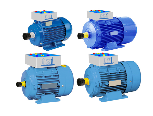
- TSI-MCL/110 Shunt/Compound DC Machine
- TSI-MCL/120 Single phase AC Motor
- TSI-MCL/130 3 Phase AC Squirrel Cage Motor
- TSI-MCL/140 3 Phase AC Synchronous Machine
- TSI-MCL/150 3 Phase Slip Ring Asynchronous Machine
All the motors and generators are intended for use in training and have a special adaptor box that brings the motor connections out onto 4mm safety sockets. A mimic diagram labels all the connection points for easy identification.
Realistic Training Application for the Motor Generator Set
Because the TSI-MCL/100 has been designed specifically for Power Training, we have include a complete power station application on the system. This allows the output from the generator to be connected to a step-up transformer.
This has an apparent power of 1,000 VA. The primary voltage for DELTA connection is 150 V, for STAR connection it is 260 V. The secondary voltages for DELTA connection are 69 -127 V, for STAR connection they are 120 - 220 V. Two methods of parallel synchronisation with the mains are also provided:
Manual
This will allow manual selection of parallel synchronisation between the output of the 3-phase generator and the power training systems simulator systems infinite power grid using a voltmeter, zero-voltmeter and a synchroscope.
The voltmeter Zero Volmeter also displays the voltage reading across the lamps and confirms the synchronised voltages before the user attempts manual closing of the paralleling switch. This system has a circuit that will automatically lock in and protect the synchronous generator.
Automatic
This mode is designed to automatically adjust the speed, voltage and phase shifting of the rotating generator in order to carryout automatic management of synchronisation and paralleling between the generator and the mains supply.
The user can make adjustment to the parameters of the controller’s PID control loops, using the control panel interface. After successful parallel synchronization it will be possible to share the load between the mains and the synchronous generator.
An outgoing HV bus system is used to connect the additional power generation simulator module to the other simulator units. The unit has two circuit breakers, one for the protection of the medium-voltage windings of the transformer and one for the protection of the high-voltage windings of the transformer.
The module is equipped with two digital multifunction 3-phase instruments for measuring voltage, current, active power, reactive power and harmonics. These have both numerical and graphical display options.
The unit is supplied in a steel mobile cabinet with a durable powder coated finish with two lockable doors on the storage area. It includes all power connection points, cables and accessories.